wheatgreaser
making a gaming engine - im 99% sure im going to regret this
i like graphics. moving things on the screen? yum. love it. i also thought it would be a good break from the web. i also like video games, ive made games(ok fuck you, unfinished miserable projects that barely pass the minimum requirement of what can be considered a game) in unity before. and i also want to do that in the future, but i really want to know how the engine actually works, and also it would allow me to build my own fucking engine whcih can be tailor made for certain types of games. i know its going to be no Unreal Engine but still. also to flex. i really want to show off my own game engine.
you can find the repo here
29 june, 2024:
ok im using OpenGL obviously. but what the fuck is OpenGL? some “people” call it a graphics API others call it a “state machine”. as i understand it, OpenGL basically provides you the tools with which you can do shit like loading a window, drawing a triangle and shit like that with the help of graphics libraries. if game engine is the tool with which you build/”run” the game, OpenGL is the tool with which you build the game engine. im following this tutorial because people call it the best.
it helps to think of OpenGL as a state machine because the things that OpenGL is dependent on its current state/context variables. for instance if we want to OpenGL to draw triangles instead of spheres we change a specifc context variable. most of the shit we do in OpenGL working with state-using functions (draw spheres) and state-switching functions(stop drawing spheres draw triangles). basically a collection of variables determines how it operates thats it.
this segment explains objects in OpenGL way better than i could:
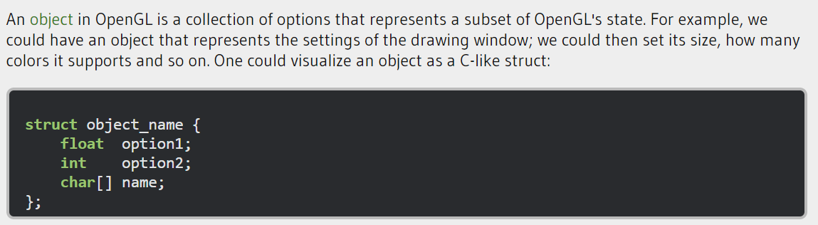
so when an object is created, we bind it to the whole OpenGL context, then we set the options (because the object is just a bunch of state variables (which are a subset of the state variables of the whole context)) and then unbind the object. for instance lets say i have a 3d model of twin towers (fly high bro), the object will just act as a container and when we want to draw the 3d model i just bind the object to the context.
opengl is such a bitch. the motherfucker cant create window, define a context or handle user input. we need another library called GLFW that does all that.
holy fucking shit. bro. it took me 1 hour to setup this whole thing. jesus fucking christ. ive never felt more like a noob, i had to install these binaries and “build” it like wtf, bro these sweaty nerds, why do they do shit like this. after an hour of hating myself, i managed to add all the libraries. AND AFTER THAT i had to fucking add these directories to visual studio, which gave me several cardiac arrests by saying “cannot run” which turned out to be beacuse it was trying to run my project which doesnt have an exe file. after this shitshow i managed to set it all up (i felt like i did molly after it worked (ive never done molly before)). lads, does this horseshit ever get easier??
now i have to create my own window. like a caveman. but its also exciting, its like im playing around with something super fundamental. ok i think i fucked up. i dont know as much c++ as i think i do. so i have to refer to the c++ docs while also doing this. brutal.
30th june, 2024:
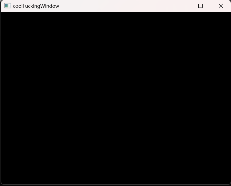
I MADE A WINDOW I MADE A WINDOW I MADE A FUCKING WINDOW HAHAHAHAH LETS FUCKING GOOOOOOOOOOOOO.
the process is actually straight forward?? like wtf. lets run through each line of the code. first we have:
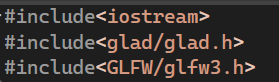
these are the header files. we already know that we use GLFW for managing windows and shit. next we have glad, glad maanages function pointers for opengl because the address of the function pointers are OS-specific and opengl is dumby-dumb and doesnt know the address of the function pointers.
next we have:
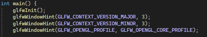
basically telling glfw that the version of opengl is 3. we also set it to core profile which only includes the modern opengl features (no backwards compatibility, womp womp). now we create the window object, like so:
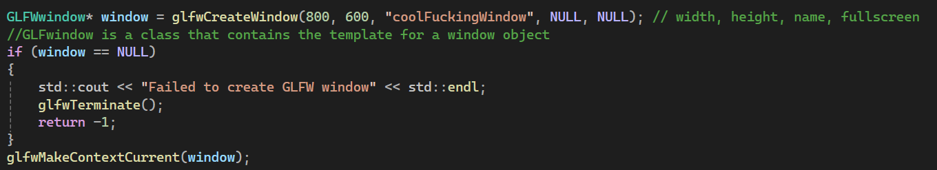
the window object holds all the data about the, you guessed it, window. i think the comments i added were self explanatory.
now we specify the position and size of the window using this:

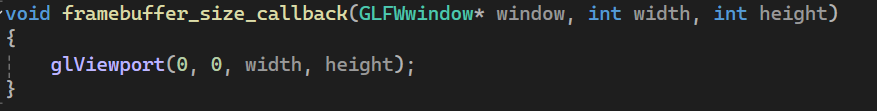
the window should also change its size and position when the user adjusts it, so we add this lil method:
technically rn we have created a window buuut if we call it rn it will just execute once and close, we need to keep it running till the user explcitly closes it, so we create something called a render loop. the render loop keeps “rendering” the window till the user explicitly stops it.
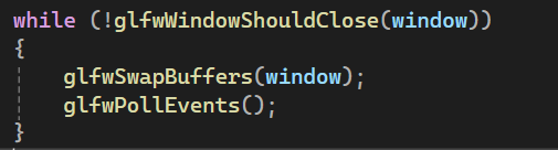
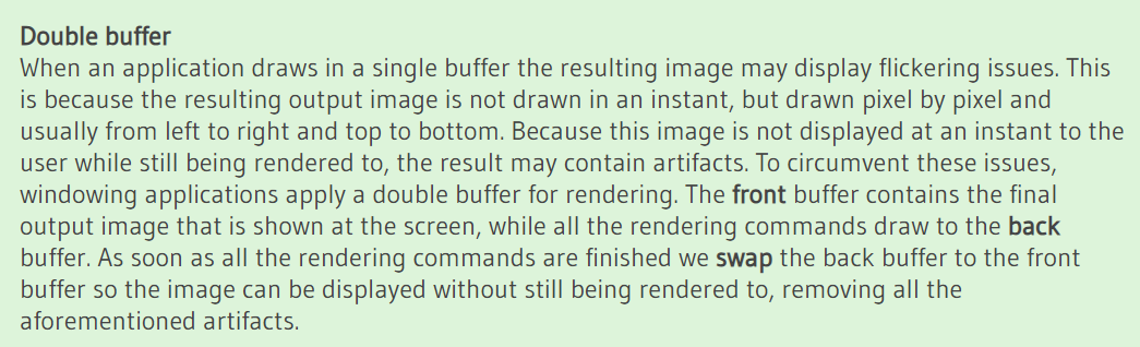
The glfwWindowShouldClose function checks at the start of each loop iteration if GLFW has been instructed to close. If so, the function returns true and the render loop stops running, after which we can close the application. the glfwPollEvents checks if there an event was triggered (keyboard input, mouse movement, etc). the swap buffer updates the color buffer of the screen. i also came across this cool snippet of how shit is actually rendered using a double buffer.
i also added things like changing the color of the screen by changing the color buffer, and i also added user input where you exit the window if you press the escape key. these two things are added part of the render loop, so it is done during each iteration (user input is checked for every iteration and the color is set during every iteration).
that was it. that was actually easier than i thought. glfw made windows like super super simple.
graphics pipeline:
the graphics pipline takes 3d coordinates and displays it as 2d colored pixels on the screen, easy right? wrong. fuck you. the graphics pipline basically has a bunch of steps linked with eachother such that the input of the current step is the output of the previous step. we can run these “steps” in parallel. each step runs a small piece of code we call them shaders. the gpus leverage the parallelness and squeeze out maximum efficiency. if you are a fucking nerd (which i assume you are because you are reading this) then you can customize the shaders, theres this language called opengl shading language with which you can customize them. ok so here’s the graphics pipeline (source):
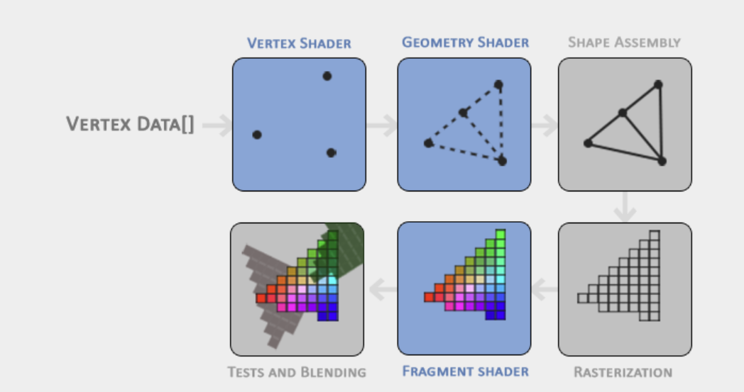
ok lets break it down.
- vertex shader: takes the 3d coordinates (which are in the form of a vertex(vectors)) and transforms them into a different set of 3d coordinates we can work with. the vertex just consists of the 3d coordinates and color.
- geometry shader (optional): basically we add other vertices to more vertices to modify the primitive shape, in the image given they added another vertex to create 2 triangles.
- primitive assembly: takes the geometry shader/vertex shader output and joins it to make a shape (2 triangles).
- rasterization stage: we map the primitives to pixels on the screen (this is the exciting part imo) resulting in fragments. fragment is all the data required by opengl to to render a single pixel(color, position, etc). we also perform clipping where we hide things out of our view to save up on resources. we then pass these fragments to the fragment shader.
- fragment shader: fragment shader finds the final color of the pixel by taking all the objects in the 3d space into account (shadows, lighting, etc).
- blending stage/alpha test: we check if the fragment is behind or in front of other objects and we have to discard the data accordingly. modern opengl is such a dick. we need to define our own vertex AND fragment shader.
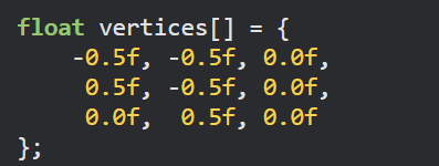
the 3d coordinate input that we give opengl is in a range b/w -1.0 and 1.0 we call this the normalized device coordinates range, any coordinates that lie out of these coordinates get clipped. the vertex data is just this:
july 2, 2024:
to send the vertex data to vertex shader we first need to allocate some memory for it in the GPU. we manage the gpu memory by using vector buffer objects, these basically process the data of the vertices all at once instead of like one at a time.

we can use different types of buffers but the one they’re using in the tutorial is a GL_ARRAY_BUFFER, which allows us to bind several buffers concurrently. now we copy the user data (the triangle vertices) into the currently bound buffer (gpu memory allocation). now we can pass several of these user defined data (datas??) simultaneously for allocation in gpu memory. now im using a GL_SATIC_DRAW argument which means the data is set once and and accessed many times (the data doesnt change). ok now we stored the vertex data in the gpu by using vertex buffer objects. NOW we can make the fucking vertex shader.
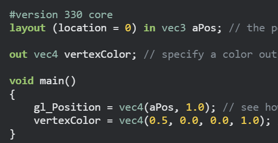
the shaders are written in a “shader language” called GLSL, whcih is like a local language for opengl shader programming. its super similar to C so it shouldnt be that big of a deal. ok so here’s the vertex shader:
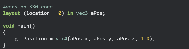
lets break it down (its hammer time (no im not 30 i just like that song)), first we specify the opengl version as 3.3 next we assign the position of the vector in “vec3” input variable (basically a mthematics vector instead of the stupid array masquerading as a vector). we also set the location of the variableas “0”. next we assign this data into a vec4 variable with the fourth argument being a bit of a mystery for now. this is called a simplified version because we did 0 preporcessing, the input data was just assumed to be in the normalized range, but in real applications thats not the case. then we compile the shader.
july 3, 2024:
now we need to write the fragment shader which is the shader that determines the final value of the pixel on the screen(by taking the whole game scene(lightning, visual effects, shadows, etc) into account (but in this “game” there is no game scene so we’re just going to be giving the fragements solid color), also technically the final final color is determined by the blending stage because obviously if an object is in front of it itll get clipped). now we’re noobs so we’re just going to be rendering a constant orange pixel for our triangle.
now we need to link all the shaders together. its like putting together different lego pieces. we do this by creating a shader program object and then linking them together, opengl basically links the output of one shader to the input of the next shader. damn i never though id say this but, opengl really makes things easy for us. i mean, look at this shit:
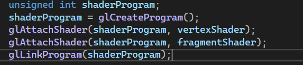
and we can start the process by using glUseProgram(shaderProgram). fucking easy. we finally delete the shader objects (i dont exactly know why).
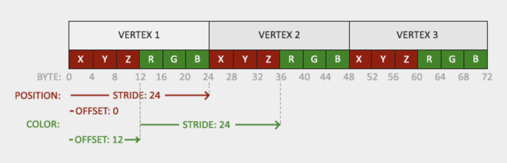
we have our shaders and the vertex data but opengl still doesnt know how to connect the vertex data to the vertex shader attributes. our vertex buffer data is stored in the gpu like this credit.
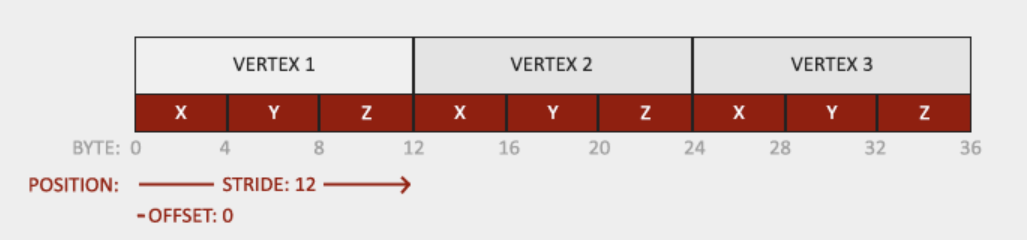
we have to take the vertex input (from the gpu memory, which we assigned to it with the help of a vertex buffer object) and take the first value and assign it to x and then the next to y and the next to z of the vertex shader vec3 thing we wrote. atleast thats how i understand it, the website skims over this part so dont blame me if i got it wrong.
now to summarize:
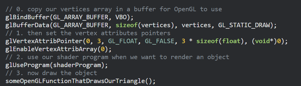
we take the vertex data assign it to gpu using a vertex buffer objects then we take it out of the memory and assign the attributes to the shader, then we start the graphics pipeline where the output of the first step is the input of the second step and then we draw the object by using some method.
now we need to make a vertex array object. i know, i know im getting sick of the vertex too but we’re almost there. i hope. im not sure what this fucking thing does. im banging my fucking head but the explanation given is so vague and cryptic. so as i understand it (take it with a pound of salt) the vertex array object just has these vertex attributes “on hand” so they can be easily assigned. maybe i’ll understand this better when i go through more advanced shit.
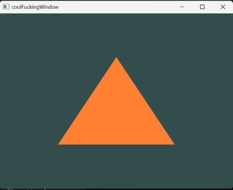
I MADE A TRIANGLE I MADE A FUCKING TRIANGLEN HAHAHAHAH LETS FUCKING GOOOOOOOOOOOOOOOOOOOOOOOOOOOOOOOOOO. but i still feel a bit icky because i dont understand the VAO part.
july 4, 2024:
i think i understand how VAOs work. they basically store the intial vertex data, it allows us to basically pass in all the data as one, for instance the color, position, etc are all combined into one object and sent in. this basically allows us to work with multiple vertex buffers easily(remember the vertex buffer object allocates the vertex data to the gpu so it needs to allocate the postion data to a part and the color data to another part, by doing this we make the allocation process easier for us).
now we NEED to make a square. since youre a fucking idiot you might be thinking that you could just create two triangles and join them, but you absolute fool there are now two duplicate vertices, did you consider that you moron?? what if i wanted to make complex model, will they all just overlapped, are we doomed to make duplicate vertices forever? no. thats where the element buffer objects come in, they use something called indexed drawing where you just specify the vertices and the order of the index in which they are to be generated. for example:
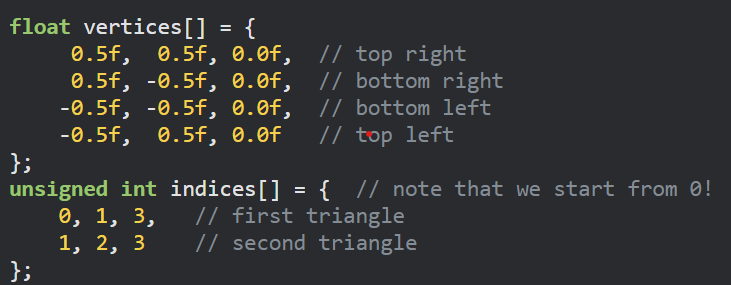
the rest of the shit remains the same.
ok so in the tutorial im following they give shit like “assignments” and im a nerd ass loser, so im going to do it. the first one seems easy: make two triangles adjacent to each eachother, this is super easy(but my method involves duplication). in the second one i have to color one triangle orange and the other one yellow. this one also seems easy because we just part one set of vertices down one pipeline with the fragment shader outputing orange color and the other set down another pipeline which contains the shader which outputs yellow color.
holy fucking shit. i accidentally corrupted the project file. I FUCKING MANAGED TO RECOVER IT USING GIT HAHA. wowoowowow. version control seems mundane till you desperately need it.
ok so the tutorial is diving deep into shaders. which i think is cool because i dont really understand glsl, the language you use for scripting shaders (its sort of like C).
the input variable in the context of the vertex shader is called a vertex attribute, this is the “vertices[]” array we pass in the beginning of the graphics pipeline.
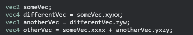
in glsl a vector is a component conatainer for instance vec3 has 3 components: x, y, and z. we also use another container called rgba for storing colors, if you recall these different things represent each pixel (position, color) and these get passed into the VAO which allocates the vec3 to a particular VBO and that assigns the first value to x the second to y and so on. there’s this cool feature in glsl called swizzling. this is where you play around with the vector components, and honestly its super intuitive.
we specify the location of the position vector (in the gpu memory) using layout location = 0 which sets the starting index of the “array” which represents the memory to be 0.
for example in this snippet the “input” is referenced as the aPos vector. we basically copy the vertex data into the aPos vector by referencing the 0th index of the gpu memory and adding 4 (because integer is four bytes) for each successive component. so 0 - 3 will be X coordinate, 4 - 7 will be the y coordinate and so on.
the fragment shader also requires a vec4 output so that we can decide the output color.
uniforms are a way to pass in data. uniforms are global so they can be accessed by any part in the pipeline.
now using uniforms i made this (ok not me i followed the tutorial) sick animation where the green value of the output of the fragment shader changes according to a sine wave (so the green color changes periodically). its nuts. lets break down the code.
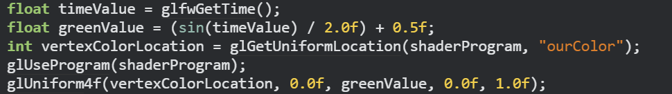
right. so we basically set the green value as a function of time using the glfw library. then we store the location(memory address) of the uniform ourColor (which contains the output color data of the fragment shader) into a variable.then we invoke the glUniform4f function which we use to set change the color at the memory address of the ourColor uniform.
you might have noticed in the last entry we just set the output as a particular color we did not recieve it as an input. i also mentioned how the VAO deals with the pos, color, etc to send them to the relevant vertex buffer object which in turns assigns them to the gpu memory. well, now we set the set the color data as an input.
july 5, 2024:
so now we specify the location of the color data using layout location = 1 (we gave location = 0 for the position data). so the memory representation looks a bit like:
now we also modify the fragment shader to let it take the color data as an input. now we get the final output as:
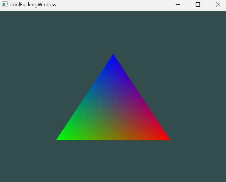
now we dont expect this output, we specified three colours so how did we get this weird ass blend. this is because of soemthing called fragment interpolation. bacially during the rasterization stage the vectors get mapped to pixels and during that process many fragments are created (not just 3) if you remember a fragment contains all the data about a pixel. now the rasterizer does something clever, it determinses the color of the fragment by taking the position of the pixel into account. for example if a pixel is in the bottom left it should be more green-y.
i just wasted 2 hours trying to configure neovim. fuck me. windows is just so ass for this type of shit. i should switch to a better OS. fuck windows. fuck this shit. 2 whole hours gone down the fucking toilet.
ok. next up we got textures, but before i dive into that i want to go through each line of the code again. because i wrote a lot of shit. i barely remember things like glfw (just kidding but still).
ok first up we got all the libraries iostream, glad and glfw. glfw is for window management and glad is for keeping track of our function pointers(for those of you new to c++ like i am, function pointers basically store the memory address of the starting part of the function we can dereference them(just like we do with a normal pointer) to call it). next we start the code by calling glfwinit() and then we specify the version and the type (core or backwards compatible) using the glwWindowHint() method. next we create a class pointer called window. the class is called GLFWwindow and is a template of the window object. we can specify the width, height and the name of the window object while calling the glfwCreateWindow() method which returns the memory address of the window object. in c++ we can access all the object data using its pointer alone. next up we set the current context (remember opengl is nothing but a state machine everything is done by assigning values to the context/state variables which determine its operation). by setting the window as the current context we set the repeective context variables which leads to the creation of a window object within the context of opengl. we also set the size of the rendering window using glViewPort(). now this method is different from the window object. this is the rendering window which means the thing visible to the user, its size CAN be different from the window object. the window object actually holds all the data. we have a method called framebuffer_size_callback that basically adjusts the viewport (the displaying/user interface part of the window) when the user makes changes to the size or position from their end. glfw provides us with a method that allows us to call this method each time the user resizes the window.
now we create something called a render loop so that the window just doesnt run once upon execution. we also constantly “poll” for user input. in this example if the user clicks “esc” the program ends.
next we create the two parts of the graphics pipeline that opengl actually wants us to do: the vertex shader and the fragment shader. we use glsl for programming the shaders.
vertex shader: first we specify the version of opengl we’re using. then we use layout (location = 0) to specify that positional data will be the “first” index of the gpu memory array. so we take the user input vertices and pass them into a VAO (vertex array object) which then takes each component/attribute seperately(the pos, the color, the texture, the etcetera) and passes them into a buffer object which assigns them to the gpu memory. so the vertex shader accesses the gpu memory and takes the data from the first index(pos data) and sotres them in a vec3 container (x, y and z coordinates). then we take the second “index” and take the data from there and store them in another vec3 container (RGB numbers). so we take these containers as inputs. we output the color as it is. then for the fragment shader we take in the color data that we outputted in the vertex shader as input and we output the final color of the pixel which is a vec4 container.
now we need to deal with the VBOs and VAOs we talked about in the previous paragraph. we first created 2 integer objects called VBO and VAO. now we create the actual VAO object by calling the glGenVertexArrays() method which takes in the memeory address of the VAO object that we created as a parameter. we call glGenBuffers() and provide the memory address of the VBO to create a vertex buffer object.we first bind the VAO to opengl (again context setting) and then we bind the vertex buffer objects. we use glBufferData() is actually the function that copies the user data in the curretnly bound buffer. remember all we’re doing is taking the user data and storing in the memory with the help of VAOs and VBOs and then the vertex shader take them from the memory and put them in little containers and they get passed around in the graphics pipeline.
uniform is a datatype in glsl which is global in nature and therefore could be used at any point in the graphics pipeline. we also came across this piece of code where it all finally clicked for me.
// position attribute
glVertexAttribPointer(0, 3, GL_FLOAT, GL_FALSE, 6 * sizeof(float), (void*)0);
glEnableVertexAttribArray(0);
// color attribute
glVertexAttribPointer(1, 3, GL_FLOAT, GL_FALSE, 6 * sizeof(float), (void*)(3* sizeof(float)));
glEnableVertexAttribArray(1);
the first part is as usual 0 offset, index = 0, etc. but in the second part we specify an offset of 3 * sizeOf(Float) whcih is the offset. so basically the x y z data and the RBG data are stored adjacent to each other. its just that when we use location = 1 we offset by 12 bytes to reach the RBG data. so location = 0 corresponds to position and location = 1 corresponds to RBG.
finally we came across fragment interpolation where we learnt that in the rasterization step many fragments are created and they are assigned a color value according to their position eventhough we only specified the color value of the 3 vertices.
its been like a week since i started opengl and i feel like ive gottn nowhere. but i play elden ring a lot so this feeling isnt all that new.
AND NOW we can tackle textures. i bet yall already know what a texture is, if youve played minecraft youd know. its basically a 2d image wrapped on top of a 2d or 3d object so as to give it detail. we need to tell opengl the correspondence between the vetex position and the position of the texture. the textures have their own coordinate system that starts at (0,0) at the bottom and left and goes upto (1,1) at the top right. so we might specify the texture coordinate corresponding to each vertex like this:
float texCoords[] = {
    0.0f, 0.0f,  // lower-left corner
    1.0f, 0.0f,  // lower-right corner
    0.5f, 1.0f   // top-center corner
};
now what if the texture map is smaller than the (0,0) to (1,1) square, well, we jsut repeat it. opengl also comes with texture filtering libraries when the textures all low-res but the object is massive.
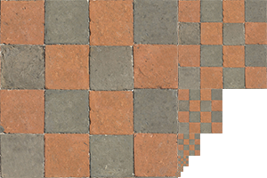
mipmap is a funny name for a depressingly mundane thing. we create textures of different resolutions and use them on the basis of distance, the closer objects are given textures with a high resolution and the ones far away are given texutres with a low resolution. the minmapped texture looks like this:
july 6, 2024:
we use a library called stb_image.h to load in the textures. we store all the data about the image in a variable. its super simple, here’s what we do, we take in the vertices as usual but this time we also add in coords for the texture data (2 numbers) then we pass that into the VAO which takes takes care of the rest (we just need to offset it by a bit nad give layout location = 2 as the index).
next we need we create a texture object that stores in all the data regarding the texture. we use glGenTextures() to actually create the texture, then we bind the texture to opengl to modify the respective context variables.
we do the texture wrapping (GL_REPEAT) and the texture filtering (GL_LINEAR). now we finally need to load in the image data into texture we created.
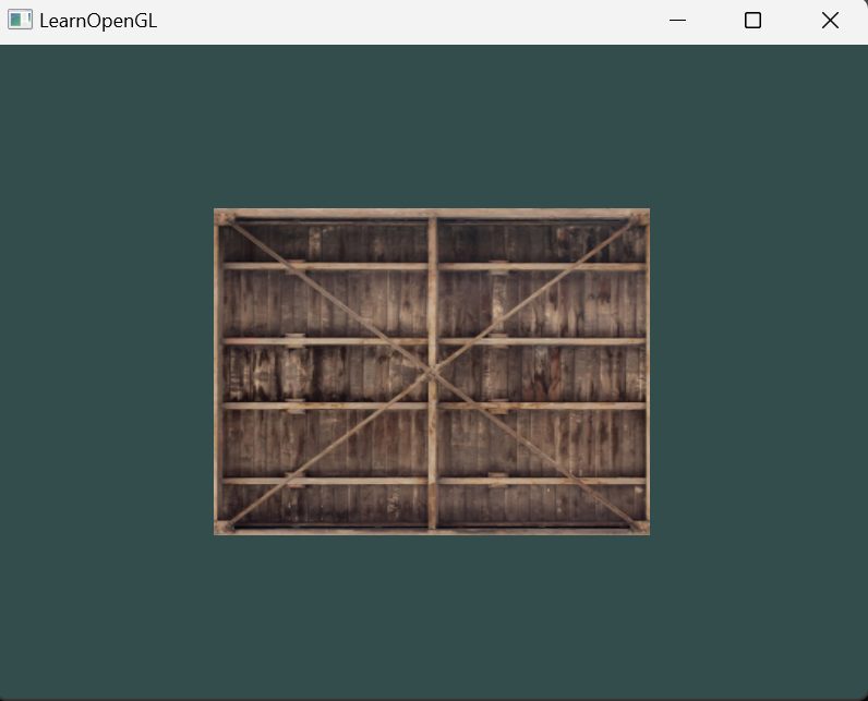
now we get to the “fun” part, the shaders. the vertex shader is the same we just pass in the same data with just the new addition of the texture data. we give it a layout location = 2 (because its the third “set” of data). we pass the color and texture dataa as it is without any modification. in the fragment shader we create a uniform sampler2D ourTexture variable. sampler2D is a datatype. GLSL comes built in with a texture() method that takes in the ourTexture (of datatype sampler2D) and TexCoord(that we recieved as inout in the pipeline) and does some magic that creates the texture to be added on top of the rectangle. again, this was extremely painful, but i can only imagine how much heavylifting is actually going on behind the scenes. so here’s the final texture wrapped object:
now we come to texture units. they basically allow us to deal with mutliple textures at once. we just use the glActiveTexture() method to set the texture unit that we want to bind. we can use them to even mix two textures together.
vector transformations everybody. we’re finally here. the fun part. here’s where we actually move things. things are about to reach the stratosphere. i dont know what got into me. i turned into a early 2000s pop punk radio host. i already learnt linear algebra in highschool so this should be easy peasy lemon squeezy.
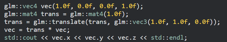
first we create a vec object in the context of glm not glsl (the vector contains 4 elements) (that should be apparent but still). next we create a unit matrix of order 4. then we use the glm::translate method that takes in the unit matrix and the vector by which it should be shifted (for example (1,2,3) means x coord will be moved by 1 and y by 2 and z by 3) to give us a new matrix that “encodes” this linear transform, we can just multiply the matrix with a vector to shift it.
this fucking header makes everything so easy that i kinda feel guilty. this shit is so easy, for example look at the scaling and rotation (where is the sine and cosine you sick son of a bitch).
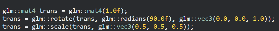
we basically rotate 90 degrees around the z axis.
to actually use this to transform our gameobject we create a uniform in the shader of the matrix type and we just mulitply it. to set the transformer as the matrix that we’ve generated we use
glUniformMatrix4fv(transformLoc, 1, GL_FALSE, glm::value_ptr(trans));
transformLoc contains the location of the transformer uniform.
july 7, 2024:
alright. so we learnt how to create a window, create different 2d shapes and add textures and colors and finally we learnt how to move them around. from here on out the tutorial goes through 3d stuff. so i want to put these things to use, you know. yes. its side project time.
march 26, 2025:
ok. I know. I know. ok so now that im kinda familiar with opengl i think we should focus on the “game engine” part of the project, because so far we’ve only dealt with the graphics stuff.